Progress on Multiple Fronts

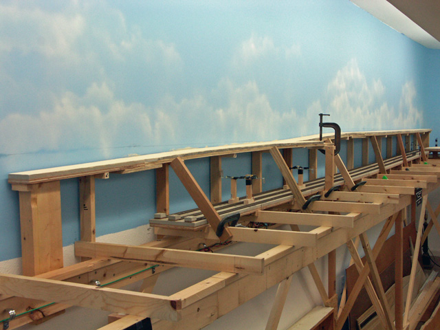
I have to admit that I’ve been in a rut for quite some time at least in regards to track laying.  And it all centers around the (self-imposed) requirement that all of the track switches are to be “DCC friendly”.  I’ve finally embarked on this project and can happily report that as a result, track work is again proceeding.  I’ve modified four of the Shinohara code 70 switches thus far, two of which have been installed.  The Illinois Central passing siding at Willis, and the interchange track to the Louisiana Central have been installed and are operational.  This completes the I.C. trackage.  The next two areas I want to complete are the L.C. passing siding at the Willis yard, and the Spencer Lumber Company’s line up to Camp 6 in the woods just east of Whitcomb.  The latter is necessary as it’s located at the far side of the benchwork in this area.  I want to get this installed and operational before advancing the Louisiana Central mainline (to be located near the aisle side of the benchwork) from Maynard to Whitcomb.

And since trackwork has resumed, I needed a fresh supply of refurbished and pre-wired Tortoise switch machines.  I grabbed another pile of those, performed the prep work, and now have them ready for installation.

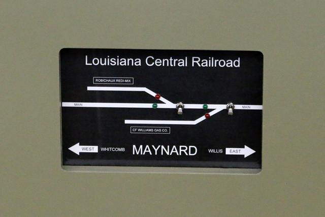
I’ve decided to go with recessed control panels similar to what I mocked up recently.  There wasn’t much point to mocking up my other ideas as the recessed version was what I really wanted and the mock-up confirmed that the idea would be workable.  This past weekend Wayne and I cut out the components for the four panels that will be in the vicinity of Maynard.  I hope to start the actual construction of these panels within a week or so.  Once these are installed, I’ll be able to paint that section of fascia.  I’m studying color samples and hope to decide on a color soon.

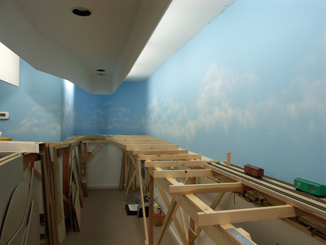
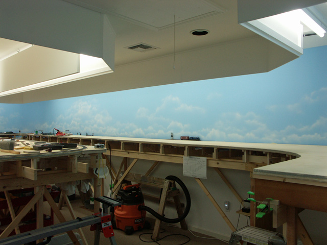
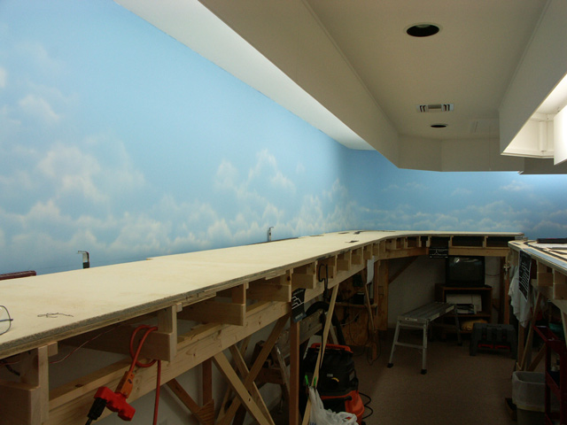
I’ve also made a minor lighting change in the train room.  In addition to the fluorescent lighting behind valances, I also have recessed can lighting over the aisles.  These have had 75 watt incandescent lamps in them.  I decided to change the incandescent lamps out to 5000k LED flood lamps, the same color temperature of the fluorescents.  These match the layout lighting quite nicely and I think it will be a visual improvement.  I also installed a twin head emergency light fixture near the entrance to the room as when the lights are out, that room gets very dark (as in black).  Interestingly, the first day after I installed the light we had a heavy thunder storm pass through and the lights went out for a couple minutes.  The emergency light did an outstanding job of lighting the way out.

And finally, freight car construction continues, although at a slightly reduced pace.  I have about 45 cars assembled and checked out to be road worthy at this point.  Only about 250 kits remain.

-Jack

A Control Panel Mock-up

I’ve been rolling ideas for control panels around in my head for several years now.  I’ve reached a point where I need to make a decision as to the style and construction I’m going to employ.  This past weekend I decided to mock up one of those panel ideas and here is the result.

Control Panel Mockup

This panel is a recessed version.  I think that this will help maximize the aisle width and also keep folks from accidentally rubbing up against the controls.  This panel is 5″ x 8″ and is typical of the size many of the panels will be.  I temporarily attached a section of Masonite to the edge of the benchwork, then cut the rough hole out for the panel.  Using 1″ x 1″ material, I “framed” the backside of the Masonite for the panel.  Using a router, I trimmed the Masonite flush with the frame, then screwed the panel to the back of it.

The panel itself is a sandwich of 1/8″ thick Masonite, a drawing, and some .093″ thick acrylic plastic.  I’ve used that method for panels in the past and they worked out well for me.

The “ghost” objects on the panel are merely reflections.  They seemed pronounced in the photo, but aren’t really noticed in person.

Opinions anyone?

-Jack

New Cars, New Overpass

I’ve rambled about assembling a big mess of car kits in the last couple posts here and here, and I’ve mentioned something about assembling a Rix Rural Timber Overpass kit.  Here’s the manufacturer’s photo of that structure:

RIX Timber Overpass

I’ve finished building the kit and it is waiting for paint.  I’ve also been working on the supporting benchwork for the bridge and I’m close to fitting it into it’s final resting spot.  The section of mainline where this will reside is just a bit west of Willis.  I’m hoping to catch the feel of the Canadian National (formerly Illinois Central) mainline in south Brookhaven, Mississippi.  There the mainline enters a stretch where it’s running in a cut in the terrain.  At the middle of this stretch is an old timber roadway overpass, not unlike the Rix kit.  The prototype bridge is a bit longer than the model, as it crosses what was once a double mainline, but the kit still captures the flavor of the structure.  I’ve always liked that bridge and hope to make this one of the signature scenes on the layout.

As for the car kits, I’ve slowed down a bit on that.  I’ve completed about 30 kits, which sounds like quite a few, but is small relative to the number of kits remaining (something approaching 300).

I’ve got all the material on hand to commence conversion work on all those code 70 Shinohara switches.  I’ve just got to muster up the motivation to get started with all those re-buildings (one of the few things that I don’t particularly want to do).  Unfortunately, the local folks around here haven’t recognized that this is potentially one of the next great model railroads.  As such, no one is beating a path to the door for the chance to become involved in its construction (a sorry state of affairs).

biggrin

Oh, I’d like to acknowledge the superior customer service that I’ve received from Accurail.  While assembling a large stack of their kits, I came across a couple that had significantly rusted up screws (used for attaching the trucks and draft gear box covers).  I contacted Accurail and they immediately sent replacement screws . . . not the eight that I’d requested, but a bag of 100.  Within a few days of my initial contact, I had product in hand.  Now that’s service!  And those extra screws have come in handy for some of the older kits.  Those older kits utilize a molded pin on the draft gear box cover which holds the cover on by friction.  I’ve modified several of these kits by cutting off the pin and drilling a hole at that location.  I then used a screw to attach the cover, greatly increasing accessibility in the event maintenance is required.

As always, comments are welcome and visits are allowed (just drop a line).

-Jack

Whupped Into Submission

Hallelujah, I finally got the entire high line sub-roadbed of the Spencer logging trackage installed.  Today I sanded out the drywall mud that I used to fill seams and screw holes, then put a coat of light dirt colored paint on top of it all.  Here’s a photo of the installation:

Spencer high line in the woods.The angled braces are temporary and will be removed after I get the rest of the sub-roadbed installed, along with scenery supporting structure.  The double switchback will connect to this level where the branch is coming off next to the clamp.  The switchback will extend about 10 feet, then will switch again to head back toward the camera, going downgrade the whole time.

This initial section along the wall looks quite simple, but it was the most difficult benchwork I’ve installed to date.  The problem was one of access, both for attaching the risers to the joists (less than three inches of working room, and at some risers, even less), and attaching the sub-roadbed to the riser cleats (not enough room to fit a drill motor needed to drill the pilot holes).  I had written about these difficulties earlier here and here.  My friend and assistant, Wayne, helped me get several risers in place, but I had to do the remainder single handed.  Not having those extra hands required me to re-think how to approach the problem.  Generally, I clamped things where they had to be, then removed the assembly from the main benchwork so that I could permanently attach those parts together with screws.  I did this in four sections until I finally got it all screwed together.

After the track switches are laid, I’ll have to remove the sub-roadbed once again (simply unscrewing it from the riser cleats) in order to install the Tortoise turnout motors and do the electrical wiring.  Again, the problem is lack of clearance to fit the drill motor needed to drill the pilot holes for the Tortoise mounting screws, and the (perceived) difficulty in getting everything aligned properly.  While this will be tedious, it will hopefully result in a much better installation of components.

Once the high line trackage is completed, I’ll put in the double switchback and the mainline run heading west back to the mill.  That should be considerably easier as that trackage won’t have anything below it.

I’ve also started laying track over in Monterey.  I figured the most critical place was the crossing located where the north leg of the wye crosses the mainline.  And that is where I started, laying the crossing, the north leg of the wye and the mainline coming in from the east, all as one unit.  Next I’ll install the north switch of the wye, and the curved switch that is at the entrance to the yard.  To see the trackplan, click this Louisiana Central Railroad link to open in another window.

I’m pleased that I’m able to make weekly progress, and with the fall approaching, I should soon garner even more time to put in on the pike.

-Jack

With a Clear Head

A couple weeks ago, I wrote about a couple snags I’d run into while test fitting some risers for the logging trackage heading up into the woods.  The problems stemmed from a lack of clearance.  I ultimately decided to walk away from the problems for the time being, then to later re-address them with a clear head.

This past weekend I had completed installing the industrial trackage over in Maynard.  I was in the process of doing the wiring below the benchwork when my able-bodied assistant Wayne called and offered some assistance for anything that needed assistance.  Not one to turn down assistance, I accepted the offer, and an hour or so later we were staring at the benchwork over at the logging site.  We floated a couple ideas around as to how to do things, then finally just got in there and started doing.  As it turned out, the problems weren’t insurmountable after all.

There’s a three inch space between the back L-girder and the wall, which my cordless drill won’t fit into.  However, I still have my very first power tool which was given to me by my dad back in the early sixties…a Ram 1/4″ drill motor.  This all metal, piece of machinery art still works just fine, and it just happened to be narrow enough to fit within that three inch space.  Great!   Wayne was able to support each riser at it’s location by pressing it firmly against the wall (sometimes using shims to adjust the alignment) while I got below to attach the riser to the joist.  Wayne was as steady as a clamp while I drilled the holes, then (with difficulty) managed to put in the screws using an old-fashioned screwdriver.  We did about nine risers, and by then my knuckles were raw from rubbing the wall and L-girder while twisting the screwdriver in those tight confines.  I have about six more risers to install, and by next weekend my knuckles should be ready for a little more abuse.  It’s all downhill after that.

The important thing here is that we found the solution, and it wasn’t complicated at all.  The solution comes after having a clear and relaxed mind…always does.  I knew this would happen…always does.

-Jack

The 2nd Anniversary

Last week I had intended to celebrate the second anniversary of the Louisiana Central’s construction, but work and other things simply got in the way.  This past weekend I spent some quiet time in the layout room and pondered what had happened over the past year.  A year ago I wrote a piece after pondering the same thing.  At the end I had stated a goal of completing the L.C. mainline by the end of the second year.  I suppose I was feeling overly optimistic that day, or perhaps my inexperience with building a large layout clouded my sensibilities.  Not only was that goal not met, it wasn’t even close!

To be truthful, I lost a couple months where I just couldn’t do any meaningful work on the layout due to some health issues.  That was followed by several more months of light duty in which some progress was made, but nothing to get excited about.  But even putting that aside, there simply was no way to get that far along in a single year with me only working on the layout during weekends.  After reading several model railroad forums, and seeing what other friends were doing, it finally helped open my eyes to what realistically can be done in a year’s time.

I’m doing much better now, and for the past three or four months, I’ve made good progress on the layout.  I also recently reduced my hours at work (semi-retirement) so have an extra day each week to put some time in on construction.  I’ve been mixing tasks during this time trying to get everything current, and also trying to avoid getting bored or overwhelmed with a single job.

The layout has five major benchwork areas: three sections along walls, and two peninsulas.  The basic L-girder benchwork for all was completed last year.  What is happening now is everything above the L-girders: joists, risers, sub-roadbed and track.  Benchwork has been completed along two of the walls and on one of the peninsulas.  This past weekend marked the construction start of the fourth section.  My friend Wayne came over and we started cutting out and placing the joists on the section of benchwork along the longest wall of the building (34′-6″).  While I hesitate to make predictions now based on my result from last year, I’m confident that these last two areas will have benchwork completed by late winter or perhaps the early spring.  Trackwork has lagged behind more than I’d like, so I want to put more emphasis on getting the track installed as well.

Here’s a pic showing the recently completed work on Saturday and Sunday.
Benwork in the AlcoveAs always, comments are welcome….drop a line!

-Jack

The Monterey Preview

OK, as promised, here are a couple shots of the recently completed benchwork at Monterey.  This first view is from the entry (at right) into Monterey. The long stretch at mid-photo is the location for the Monterey yard.  The Georgia-Pacific kraft paper and box plant will be further down where the soldering station and tools are.  The benchwork sticking out on the lower left is the Willis yard peninsula.

Monterey, looking westThe photo below is taken from the other end of Monterey yard.  The G-P plant will be to my far left (out of view).  Those strange objects sticking up along the wall are the metal brackets supporting the infra-red LEDs used for the photo detection system on the staging tracks.  They’re located over the partially recessed (and to be hidden) Texas and Pacific track.  That’s the top of a boxcar just visible at the left.

Monterey, looking eastThese, and several other photos appear on the main website.  Click here to visit.

-Jack

Assaulting Homasote Joints

Regular readers will recall the disaster I incurred in my attempt to use a belt sander for tapering roadbed and truing joints between Homasote sheets (Banning the Belt).  In laying the sub-roadbed for Monterey, which is essentially a Homasote tabletop, I was faced with three wide joints with a significant mismatch in height.  As I’ve mentioned several times, Homasote isn’t known for its consistency in thickness.  These height mismatches between panels were as great as a 16th of an inch…much too great to simply lay track, or even roadbed and track over.

Hand sanding large expanses of Homasote isn’t practical.  It just doesn’t sand like wood.  This past weekend I knew I had to get these joints matched up before track laying could commence.  So I tried another approach to the problem.  I had a Surform tool in my toolbox so I tried it out.  Surprise, it actually started shaving off the Homasote.  Now, it wasn’t pretty.  It actually grabs little chunks of Homasote and rips them out.  The tool clogged quickly, but a small stiff bristle brush worked well to clean it up.  I didn’t want to simply do a quick taper right at the joint, but rather I wanted a gradual taper of at least 3-4 inches in width.

Once I got it fairly close with the Surform tool, I decided to try my finish sander for the final sanding.  I attached some 50 grit paper (pretty coarse for a finish sander) and started working the surface.  This worked out much of the roughness created by the Surform tool.  I worked it for quite some time and ended up with a pretty decent taper and surface.

The final step was to smear a coat of drywall mud over the joint, building up from the formerly thinner side of Homasote up to the joint.  I’ll sand this down tonight and apply another coat.  After doing this two or three times, I should have a pretty decent joint between the panels and will be satisfied.

It was several hours of work, but in the end I think it’ll be worth it.  Did I mention the layer of fluffy dust over that area of the room to clean up?

On another note, I had intended to keep my electrical wiring current with the track laying.  But I’d let the wiring slip over these past couple months.  Surveying under the layout, I realized that there were about two dozen sets of track feeders that hadn’t been connected to the power bus yet.  I took the first step in installing the terminal blocks at each location (which serve as the interface/disconnect between the feeds and the bus), and I crimped spade lugs on all of the feeders.  Over the next weekend or two I’ll make taps into the power bus and run the heavy gauge taps to the terminal blocks.  My method, though tedious, works quite well and should result in dependable wiring that will also be easy to troubleshoot when necessary.

All in all, a pretty busy weekend especially since I was away from home most of Saturday.

-Jack

Monterey Yard Sub-roadbed Complete (and other things)

Things have been pretty busy around the Louisiana Central these past weeks.  Since completing the lift-up access section a few weeks ago, I’ve gotten the remainder of the sub-roadbed down for the yard at Monterey.  This completes the benchwork along the east wall of the building and represents about three-fifths of the total area of layout.  The west wall and the second of the two peninsulas will not have so much “table top” sub-roadbed, but will be heavy in the single track variety as this is where much of the mainline is located.

This past weekend, Wayne and I mocked up the Spencer Lumber Company’s line up into the woods.  This is the trackage that will be over (and will conceal) the three track staging yard along the west wall of the layout.  I’ve had concerns over the accessibility of these tracks since the day I started construction.  The track will be reachable from below the benchwork, but not easily visible.  I’m hoping that the crude mock-up we’ve erected will enable me to study the concept satisfactorily, and to make the decision to go with it or not.

Next weekend I’m expecting a visit from a fellow hobbyist from Florida.  I had planned to clean and straighten up around the layout in anticipation of his visit, however, lack of time will likely kill that plan…hope he understands.  I also need to take some time to visit the library that is currently hosting an exhibition of photographs taken by local photographer Forrest Becht.  Forrest takes images of many things, but railroads are his specialty and I always enjoy viewing his work.

There’s a fellow up in Canada, Trevor Marshall, that is building an S scale pike based on a Canadian National branchline set back in the 1950s.  I believe I’ve mentioned him before in this blog.  Anyway, Trevor maintains a blog chronicling the construction and operation of his mini-empire, along with other little tidbits about what’s going on in his world.  I really admire Trevor’s approach to the hobby and many of the things he does to model the CN branch and to enhance his operations.  I also enjoy his writing style and the variety of topics he rambles about.  If you’d like to give his blog a look-see, you’ll find it here: Port Rowan in S Scale.  To quote Trevor, “Enjoy if you visit“.

-Jack

Two Steps Forward, One Back

I’ve been making some fairly good progress on the layout these past several weeks.  The mainline track has been completed through the Willis yard and is now about halfway around the orb of the peninsula at the west end of Willis.  Eight feet of sub-roadbed (table top in this instance) has been installed at the east end of Monterey.  The hidden staging track for the Texas and Pacific will emerge onto the layout and connect at this section of benchwork.  There’s about a ten foot span remaining between the two benchwork sections now completed at each end of the Monterey area.  I’ll get to that in the next few weeks.

Space in this corner of the layout is pretty tight.  During the installation of the joists and risers for this section, I found it necessary to adjust the location of several joists to facilitate enough access to fasten them to the L-girders.  More about this below.

The plywood/Homasote table top just installed here will contain a pop-up (lift) section.  This will be needed so that I can access the tail track of the wye planned for this area.  The first thing I did after temporarily clamping the table top in place was to lay out all the trackage here.  I then marked out the location of the hole required for the pop-up.  After doing this, I decided to check the future locations underneath for the Tortoise turnout motors that I’d be using.  Surprise!

There are twelve switches in this section.  Two of them have the switch rod (the throw bar) located above risers.  Four more are very close and may require moving or modification of the risers.  Rats!

I had carefully laid out the locations of joists and risers on paper, taking into account the locations for the Tortoises below.  But I conveniently forgot about all this great planning while gleefully sliding the joists about to make fastening them easier.  At least the required adjustments will be simpler to make since I’ll be removing the table top to cut out the hole for the pop-up.

And so it goes.  But despite the setback, I still got a step further out in the long run!

-Jack

Banning the Belt

Work has picked up on the Louisiana Central these past weeks.  Mainline trackage is going down through Willis yard and will be heading west beyond Willis within a few weeks.  This represents the first trackage of the Louisiana Central beyond the staging areas onto the visible portion of the layout.  In addition, the first industrial spur track on the layout has been installed.

The initial 8 feet of sub-roadbed (tabletop) has been installed in West Monterey.  This will be the area with the large plywood and paper mill complexes that will be the basis for the loads in/empties out scenario.  I’ll be starting with the sub-roadbed at the east end of Monterey soon, building toward the center of the Monterey area.  I’d like to get a little more work done and will then update the website with a few more photos showing the latest progress.

I’ve made the decision to ban my belt sander from the layout.  Three times I’ve tried using it to sand Homasote panel joints to even the ends and the results weren’t very good, requiring a judicious application of drywall mud to even and level out the area afterward.  My most recent effort was trying to sand a taper into the cork roadbed where it butted up to some Homabed roadbed of a lesser thickness.  Despite partially supporting the sander above the work and just applying a few “bumps” of the trigger, I still managed to gouge everything badly.  I’ll try to use the drywall mud again to fill and level the area.  If that doesn’t work, I’ll have to scrape out about 16″ of roadbed and start over.  When will I learn?

We’ve had an unusually cold winter thus far, but the train room has remained warm and cozy through it all.  Having worked through both hot, humid summers and cold winters in the room, I can say the heavy insulation and weatherproofing of the building has paid off.  It’s a pleasure working in it’s comfortable environment.

Again, I extend the invitation to anyone interested in seeing the layout to come by for a visit…just give me a buzz or drop me an email and we’ll set something up.

-Jack

Forging Ahead

While my medical woes are still ongoing, I manage to get some work done each weekend on the layout.  This past weekend I even got a nice chunk of sub-roadbed installed; the mainline heading west out of Willis yard.  It was satisfying to cut wood again and assemble risers and sub-roadbed.  As is my habit, I topped the plywood sub-roadbed with a layer of Homasote.  Track can now be laid here.

I’ve pretty much finalized the layout for all of the controls panels that I spoke of in the previous post.  I’m going to build a “test” panel and verify that I’m satisfied with the design.  I’m still toying around with the method that I will use to mount the panels to the fascia.  The test panel will be helpful in my experiments with that.

With winter just around the corner, I’ve been giving thought to making a couple field trips.  I’d like to once again travel the planned route of the Louisiana Central to grab a few more photos.  Wayne Robichaux and I have already done this a couple times back when I was planning the layout.  We tentatively laid out the track route on a map, then set out to see how closely we could actually follow that route.  We made tweaks to the route on the map as we traveled, and the plan came out rather well.  You can take a photographic journey of this route on the main website.

The other field trip I’d like to take is to the Southern Forest Heritage Museum up in Long Leaf.  This museum features the former Crowell Long Leaf Lumber Company’s mill operation.  I’ve written about this place in an earlier post, and I love to visit there.  The Spencer Lumber Company on my layout will be loosely based on the Crowell mill.  I don’t plan to model the specific structures at Long Leaf, but seeing and understanding the operation and the flow of the work will aid me in laying out a reasonable mill site on my layout.  I’ve already taken dozens of photos, but want many more.

As always, give me a holler if you’d like to visit or if you have any questions.

-Jack