LCRR Avatar

About Jack Shall

I've been a model railroader and railfan for well over 60 years now. My interests lie in the steam era and the early diesel era. My modeling has been in HO, but I do have a closet interest in Fn3 :-) It's been a number of years since I've done any layout construction, and the new Louisiana Central pike under construction is by far my most ambitious effort. Follow along with me on this new adventure of the Louisiana Central.

Optical Detection Explained

Well, there I go again.  Earlier I posted a column celebrating the completion of all the hardware and wiring for my optical detection system (well, it’s not really complete….I still have to build the panels that will display the occupancy indicator LEDs).

Problem is, I just assumed all readers would know what I was talking about.  Not!  I’ve been informed that I should quit assuming.

So, I’ll try to explain in 3000 words or less, just what an optical detection system is.  Now keep in mind that my explanation here is strictly in the context in which I am employing said detection system.  And I will avoid getting into the directions that the electrons are traveling and the gory details of the circuitry that makes this all happen.

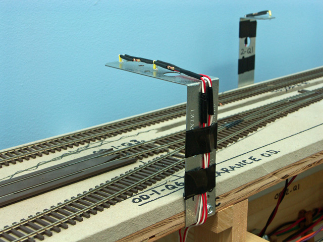
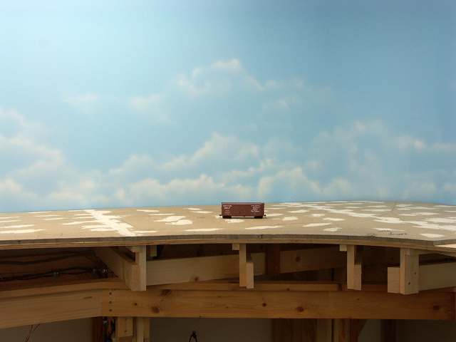
I have six staging tracks, all of which are hidden from normal viewing.  In order to ascertain where a train is while running on this track, I decided to employ a detection system.  There are several ways to detect a train, and I chose to employ optical detection.  The system utilizes photo-transistors (PTs) which can sense whether or not they are seeing light.  When they do, they will turn on, that is, they act as a switch and will close a circuit.  I have installed my PTs centered in the track between a pair of ties, with their tops just above the roadbed.  The PTs are wired to a circuit board located under the layout.

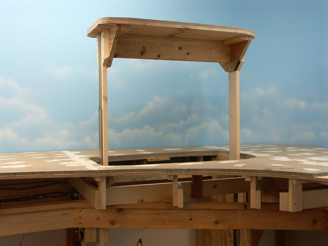
As a light source, I’m using infrared LEDs (IR-LEDs).  To avoid seeing light beneath the layout, and to make the circuit less susceptible to ambient lighting, I chose to use components that are sensitive to light in the infrared range.  This isn’t visible to the naked eye, and in fact, that’s what most TV remote controls use.  The PTs and the IR-LEDs selected are matched to their light spectrum and work in harmony together.  The IR-LEDs are mounted on the “towers” I spoke of in the last post, and are pointed down at the PTs.  They are simply wired to a 12 volt DC bus (a pair of wires).

The circuit board I mentioned above is the “brain” of the system.  The inputs to the board are the PTs.  The outputs are to plain old red LEDs which are used as indicators, installed on a simple panel with a track diagram.  Each indicator LED is placed on the track diagram at the location where a PT sensor is located on the actual track.

With the power on and the IR-LEDs shining brightly, the PTs see the light and the circuit board determines there is nothing out there as no PT is “closed”.  Therefore, no power is supplied to the indicator LEDs on the panel.  But when a train comes along, it blocks the light of an IR-LED shining on a PT below, and that PT turns on, which in turn lets the circuit board know that something is at that location.  It in turn lights up the appropriate panel indicator LED and you now have a visual indication of where the train is.

Simple, huh?

Actually, it really is.  I purchased the circuit boards already built up from a fellow hobbyist up in Canada.  All I had to do was install the PTs and IR-LEDs, and wire them up.

Your test will arrive in the mail later in the week.

-Jack

Optical Detectors Installed

I can hardly believe it myself.  I’ve completed the installation of all 24 of the photo-transistors (herein known as PTs) and their accompanying infrared LEDs (IR-LEDs) as used in my optical detection system.  Whew, what a job!  Nothing about the project was particularly difficult…at least not on paper.  The premise was simple, the wiring was simple, the hardware was simple.  But the effort to do each task wasn’t trivial, and the collective effort expended was nothing short of colossal.

Installing the PTs was by far the fastest and easiest thing to do.  Simply drill a 3/16″ hole and stick the PT into it.  Didn’t even have to secure them…they are held by friction.  I then ran a 26 pair phone cable around the layout and tapped into it with the PT leads, each PT on it’s own circuit.  The cable ends at a backboard beneath the layout where the circuit cards are located.  I made the tie-ins and the detection circuit was complete.

The IR-LEDs required much more effort.  The IR-LEDs are used as the illumination for the PTs.  I chose to install these up over the track, with the LEDs pointed down over the PTs.  I ended up fabricating a “tower” for each IR-LED.  In fact, I actually fabricated three types of towers as required by different installation requirements.  Using flat metal framing straps procured from Home Depot, the fabrication involved was drilling a couple holes, making some bends in the metal, then installing the towers onto the benchwork.  Later I made up some assemblies, each consisting of an IR-LED, a current limiting resistor, and some wire leads.  I installed these on the towers, ran the leads down below the sub-roadbed, and attached them to the 12 volt DC bus.

Today I applied the power, checked that each IR-LED was in fact illuminated (had to use my digital camera for that since you can’t see light emitted from them with the naked eye), then rolled a boxcar through all the “traps”.  All worked perfectly with no adjustments required!

Here’s a photo of a couple of the towers.  The one in the foreground is a double tower, in that it supports two IR-LEDs (one over each track).  If you go over to the main website, I have photos of all three types.

IR-LED Support TowerThere is one final task to do before the system is operational, and that is to build three small panels which will contain track diagrams with red LEDs located at appropriate locations.  This will be the visual indication to the engineer as to where his train is on the hidden staging track, and most importantly, when to stop.  I  need to install the fascia before building and installing the panels, so that task will be a ways down the road.

But having the hardware installed over the staging tracks clears the way for me to start the sub-roadbed and trackwork for the upper level above.

Progress is surely sweet!

-Jack

The 2nd Anniversary

Last week I had intended to celebrate the second anniversary of the Louisiana Central’s construction, but work and other things simply got in the way.  This past weekend I spent some quiet time in the layout room and pondered what had happened over the past year.  A year ago I wrote a piece after pondering the same thing.  At the end I had stated a goal of completing the L.C. mainline by the end of the second year.  I suppose I was feeling overly optimistic that day, or perhaps my inexperience with building a large layout clouded my sensibilities.  Not only was that goal not met, it wasn’t even close!

To be truthful, I lost a couple months where I just couldn’t do any meaningful work on the layout due to some health issues.  That was followed by several more months of light duty in which some progress was made, but nothing to get excited about.  But even putting that aside, there simply was no way to get that far along in a single year with me only working on the layout during weekends.  After reading several model railroad forums, and seeing what other friends were doing, it finally helped open my eyes to what realistically can be done in a year’s time.

I’m doing much better now, and for the past three or four months, I’ve made good progress on the layout.  I also recently reduced my hours at work (semi-retirement) so have an extra day each week to put some time in on construction.  I’ve been mixing tasks during this time trying to get everything current, and also trying to avoid getting bored or overwhelmed with a single job.

The layout has five major benchwork areas: three sections along walls, and two peninsulas.  The basic L-girder benchwork for all was completed last year.  What is happening now is everything above the L-girders: joists, risers, sub-roadbed and track.  Benchwork has been completed along two of the walls and on one of the peninsulas.  This past weekend marked the construction start of the fourth section.  My friend Wayne came over and we started cutting out and placing the joists on the section of benchwork along the longest wall of the building (34′-6″).  While I hesitate to make predictions now based on my result from last year, I’m confident that these last two areas will have benchwork completed by late winter or perhaps the early spring.  Trackwork has lagged behind more than I’d like, so I want to put more emphasis on getting the track installed as well.

Here’s a pic showing the recently completed work on Saturday and Sunday.
Benwork in the AlcoveAs always, comments are welcome….drop a line!

-Jack

The Monterey Preview

OK, as promised, here are a couple shots of the recently completed benchwork at Monterey.  This first view is from the entry (at right) into Monterey. The long stretch at mid-photo is the location for the Monterey yard.  The Georgia-Pacific kraft paper and box plant will be further down where the soldering station and tools are.  The benchwork sticking out on the lower left is the Willis yard peninsula.

Monterey, looking westThe photo below is taken from the other end of Monterey yard.  The G-P plant will be to my far left (out of view).  Those strange objects sticking up along the wall are the metal brackets supporting the infra-red LEDs used for the photo detection system on the staging tracks.  They’re located over the partially recessed (and to be hidden) Texas and Pacific track.  That’s the top of a boxcar just visible at the left.

Monterey, looking eastThese, and several other photos appear on the main website.  Click here to visit.

-Jack

Progress Non-indicators

I’ve been hesitant to write anything about what I’ve been up to for a couple weeks now for fear that it would be –well– boring.  I’ve been spending an awful lot of time doing things that don’t really show up or add visible progress to the layout.  For example, I’ve been hard at work installing the optical detection system for the hidden staging tracks at Willis and under the Spencer logging operation up in the woods.  That alone has been quite a chore, including fabricating support brackets for the illumination LEDs, bus runs of wire, wiring dozens of photo-transistors and LEDs, and more.  When complete, not a single soul is likely to bend over and look into the dark recesses at the back of the layout to see that system (they likely won’t even know that it exists).

Then there are the power buses and dozens of track feeders to same.  Again, a very necessary endeavor, but entirely unnoticed by crew or visitors.

I spent quite a bit of time creating gently sloped ramps for the mainline at Monterey to get the various yard and industrial tracks from the elevated roadbed down to the tabletop.  It’s all done now and waiting for track.  Even though that work is visible, it is very likely to go unnoticed.  And how about those track bumpers that I manufactured and installed on the ends of all six staging tracks?

And so it goes.  I can list another half dozen projects that I’ve undertaken and completed these last several weeks, and not one will garner any attention by those who casually peruse the layout.  And none will likely be photographed and immortalized on the website.

Those of you that have constructed, or are constructing a larger sized layout know exactly what I mean by all of this.  Everything I’ve done is necessary for the operation of the layout.  But I confess to being a little depressed about putting in so much time doing things that do little to reward you with a feeling of accomplishment (well, there is the self-satisfaction of having done the chore and scratching it from the list).

However . . . things are looking up for the near future.  Once the detector work is completed (and it’s not terribly far off), the sub-roadbed construction can again proceed.  And I now have several areas where a bit of track may be laid, and that’s always something that gets attention.  Gratification time is getting near!

In truth, there has been some visible work.  I’ve completed all of the benchwork and sub-roadbed for Monterey and the area immediately to the east, including it’s roadbed (with tapers), and all is covered in a nice coat of paint.  I suppose I should take some photos and post them to the main website.  Maybe I can get to that by the weekend.  Now that would be gratifying!

-Jack

Fascia Anyone?

I need to be thinking about putting up parts of the fascia around the layout.  The fascia will be much more than just a nice piece of trim on the layout’s edge.  It will be supporting the various control panels, throttle plug-ins, beverage holders and various appurtenances as I may think of in the future.

But I can’t reasonably start any type of train operation until I get at least a few panels installed and a hand full of the throttle plug-ins.  Thus, I need some fascia.

The fascia will average 8″ in height, the top undulating to match the terrain and elevation at any given location…pretty standard fare.  I plan to use Masonite hardboard for the fascia, and have been thinking of laminating two 1/8″ thick panels together.  My reasons for this two-ply configuration are twofold: I think working 1/8″ material around a tight radius will be much easier than using 1/4″, and the two plies should give me the rigidity of a single 1/4″ panel.

My general plan is to screw the first panel to support blocking on the benchwork.  Then I’ll come back and glue the second panel to the first using yellow carpenter’s glue.  Clamping the panels together until the glue sets is a bit problematic.  I’ll be able to clamp along the bottom of the fascia, but will probably have to use some screws along the top to clamp that.  The downside to that would be having to remove the screws and fill all those holes afterwards if I wish to keep the fascia “clean”.

I’d love to hear from you folks out there if you have other ideas or suggestions as to how I might accomplish this task.  It would be good having alternatives to think about.  Any thoughts would be welcome, everything from materials to methods.

-Jack

Assaulting Homasote Joints

Regular readers will recall the disaster I incurred in my attempt to use a belt sander for tapering roadbed and truing joints between Homasote sheets (Banning the Belt).  In laying the sub-roadbed for Monterey, which is essentially a Homasote tabletop, I was faced with three wide joints with a significant mismatch in height.  As I’ve mentioned several times, Homasote isn’t known for its consistency in thickness.  These height mismatches between panels were as great as a 16th of an inch…much too great to simply lay track, or even roadbed and track over.

Hand sanding large expanses of Homasote isn’t practical.  It just doesn’t sand like wood.  This past weekend I knew I had to get these joints matched up before track laying could commence.  So I tried another approach to the problem.  I had a Surform tool in my toolbox so I tried it out.  Surprise, it actually started shaving off the Homasote.  Now, it wasn’t pretty.  It actually grabs little chunks of Homasote and rips them out.  The tool clogged quickly, but a small stiff bristle brush worked well to clean it up.  I didn’t want to simply do a quick taper right at the joint, but rather I wanted a gradual taper of at least 3-4 inches in width.

Once I got it fairly close with the Surform tool, I decided to try my finish sander for the final sanding.  I attached some 50 grit paper (pretty coarse for a finish sander) and started working the surface.  This worked out much of the roughness created by the Surform tool.  I worked it for quite some time and ended up with a pretty decent taper and surface.

The final step was to smear a coat of drywall mud over the joint, building up from the formerly thinner side of Homasote up to the joint.  I’ll sand this down tonight and apply another coat.  After doing this two or three times, I should have a pretty decent joint between the panels and will be satisfied.

It was several hours of work, but in the end I think it’ll be worth it.  Did I mention the layer of fluffy dust over that area of the room to clean up?

On another note, I had intended to keep my electrical wiring current with the track laying.  But I’d let the wiring slip over these past couple months.  Surveying under the layout, I realized that there were about two dozen sets of track feeders that hadn’t been connected to the power bus yet.  I took the first step in installing the terminal blocks at each location (which serve as the interface/disconnect between the feeds and the bus), and I crimped spade lugs on all of the feeders.  Over the next weekend or two I’ll make taps into the power bus and run the heavy gauge taps to the terminal blocks.  My method, though tedious, works quite well and should result in dependable wiring that will also be easy to troubleshoot when necessary.

All in all, a pretty busy weekend especially since I was away from home most of Saturday.

-Jack

Those Optical Detectors

There are six hidden staging tracks serving the Louisiana Central.  Since the tracks are concealed from normal viewing, I decided to use optical detectors at each track to determine occupancy and the locations of trains.  Typically each track has two or three detectors near its end, and one at the entrance marking the fouling point.

Two of those staging tracks are in Monterey, one each for the IC and the T&P.  This weekend I completed the wiring for the photo-transistors and infrared (IR) LEDs, and their connections to the circuit board serving this area.  The fascia panel with the indicators isn’t built yet, so I soldered a couple leads to a red LED indicator and temporarily jumped it across the various output terminals for testing.  I’m happy to report that all the detectors worked perfectly without a single adjustment necessary.  This is somewhat a milestone in the electrical/electronics portion of the layout construction.  There are two more circuit boards over at the Willis side to handle the rest of the staging tracks.  I’ve got most of the photo-transistors already wired, but I need to get all the IR LEDs installed.  Benchwork for the Spencer logging operation can’t proceed until that work is done as most of the staging track is below that, and I want the system complete and operational before starting this new benchwork.

I had a busy weekend working on the layout.  In addition to the above, Wayne and I got the remainder of the sub-roadbed installed in East Monterey (not an official designation).  This area is around the corner from Monterey itself and will support the mainline entering town as well as a couple businesses.

I also got some roadbed laid near the end of the Monterey yard and I took care of a half dozen little tasks that I’d been putting off.  Overall, a good weekend.

Finally, my scheduled visit by a guest from Florida was cancelled due to some family health issues, but I got a semi-surprise visit instead from a co-worker, Van Thomas.  Van has been hearing about my construction for the past couple years and he decided to come over to see what this was all about first hand.  I think he enjoyed the visit, despite the hot and heavy construction going on during his stay.

-Jack

Monterey Yard Sub-roadbed Complete (and other things)

Things have been pretty busy around the Louisiana Central these past weeks.  Since completing the lift-up access section a few weeks ago, I’ve gotten the remainder of the sub-roadbed down for the yard at Monterey.  This completes the benchwork along the east wall of the building and represents about three-fifths of the total area of layout.  The west wall and the second of the two peninsulas will not have so much “table top” sub-roadbed, but will be heavy in the single track variety as this is where much of the mainline is located.

This past weekend, Wayne and I mocked up the Spencer Lumber Company’s line up into the woods.  This is the trackage that will be over (and will conceal) the three track staging yard along the west wall of the layout.  I’ve had concerns over the accessibility of these tracks since the day I started construction.  The track will be reachable from below the benchwork, but not easily visible.  I’m hoping that the crude mock-up we’ve erected will enable me to study the concept satisfactorily, and to make the decision to go with it or not.

Next weekend I’m expecting a visit from a fellow hobbyist from Florida.  I had planned to clean and straighten up around the layout in anticipation of his visit, however, lack of time will likely kill that plan…hope he understands.  I also need to take some time to visit the library that is currently hosting an exhibition of photographs taken by local photographer Forrest Becht.  Forrest takes images of many things, but railroads are his specialty and I always enjoy viewing his work.

There’s a fellow up in Canada, Trevor Marshall, that is building an S scale pike based on a Canadian National branchline set back in the 1950s.  I believe I’ve mentioned him before in this blog.  Anyway, Trevor maintains a blog chronicling the construction and operation of his mini-empire, along with other little tidbits about what’s going on in his world.  I really admire Trevor’s approach to the hobby and many of the things he does to model the CN branch and to enhance his operations.  I also enjoy his writing style and the variety of topics he rambles about.  If you’d like to give his blog a look-see, you’ll find it here: Port Rowan in S Scale.  To quote Trevor, “Enjoy if you visit“.

-Jack

Trains Roll on the Attighany Sub

Back in April I mentioned the possibility of continued operations on the late Lou Schultz’s Chesapeake and Ohio layout (Maybe the Sun Hasn’t Set).  Well possibility became reality this past Saturday as many of the former operating group assembled once again in Covington.  Yes, trains once again rolled on the Attighany Sub (an unofficial term often used for the layout).

We ran what was termed a “test” session.  We had a reduced crew of 16 and ran a four hour session.  The local organizers had pre-staged the layout and cleaned the track.  The fast clock was plugged in at 12:01 p.m., and trains started moving.

As was expected, there were a few glitches, some operational, some electrical/mechanical.  But considering that the layout had been dormant for over a year and that no one there had ever staged the layout before, things ran surprisingly well.

It was great seeing old friends again.  I think I speak for most everyone in saying that we want to continue doing this.  But there was also a sadness in not having Lou, Bill and Shawn present.

Our heartfelt thanks go out to Lou’s wife, Dee, and the family for their kindness and the opportunity to keep Lou’s dream alive.

On the way back home, Wayne Robichaux and I analyzed the session and stopped to partake of a meal at the Lagniappe Restaurant in Denham Springs.  What a way to spend and end the day . . . a fine day indeed!

-Jack

Sneaking Into Monterey

One can now sneak into Monterey via a subterranean entrance.  I completed the lift-up section this weekend.  Now I’ve got reasonable access back to the tail track of the wye and the surrounding area.

Lift-up section - closedAbove: Here’s the lift-up in the closed position.  The seams are very tight (merely the thickness of a jigsaw blade).  The wye will be to the right of the lift-up.

Below: And here’s the view of the lift-up in the raised position.  The center cross brace is about 3″ above my head.  I can comfortably reach the corner over to the right now.

Lift-up section - openThe drawer slides I used have release latches in them and it’s easy to lift the hatch and support legs completely out of the hole.  After setting the assembly aside, the area all around the hole is completely unobstructed.  I also can then stand on a stool if need be to enable an even further reach into the corner and to get my tired old eyes closer to the work.  That might be useful when scenery work begins.  There are a few more photos you can view here on the main website.

The lift-up works quite well, is easy to operate, and I’m very pleased with it.

-Jack

A Visit to the Narrow Gauge

This past weekend Wayne Robichaux and I paid a visit to a friend, Bob McNeese, to pick up some Homasote left-overs that he had from his nearly finished layout.  While there, Bob gave us a tour of his pike and I must say, it is something to behold.

It’s in Sn3 scale and is generally based on the former Rio Grande’s narrow gauge operation in the New Mexico/Colorado area.  The layout has a couple small yards, and silver mines abound.  The structures are superb, the layout’s level of detail is quite high and the scenery is spectacular.  There was simply no way to take it all in with just one visit and I’ve already told Bob that I need to visit again to continue my observation.

The proponents of S scale often tout the fact that it is the “ideal” scale, and I have to agree.  I love the size with respect to actually being able to see the finest details, yet still small enough to get a decent sized layout in a modest space.  If I didn’t have 50 years worth of HO collected and was just getting started, I’d have to give S scale some serious consideration.

On the Louisiana Central, a modest amount of work has been accomplished since my last post.  The framing around the lift-up access hatch is done and the drawer slides are installed.  I need a couple more hours to complete the framing required on the hatch section itself to connect it to the drawer slides.

I’ve completed the short run of sub-roadbed needed to tie the Texas and Pacific trackage from staging, into the main sub-roadbed at Monterey.  I’ve extended the T&P track from staging onto the visible portion of the layout, just shy of the yard.

And I’ve advanced the track into Maynard a bit.  I’ve been preparing the two switches that will be required there, and should have those installed shortly.  Further progression of the mainline will be a bit down the road.  I want to start work on the Spencer Lumber Company’s trackage into the woods and the reload point before putting in the LC trackage.  This is because the LC track will be in the foreground and I prefer working from the wall out toward the aisle.  Hence, the logging line needs to be first up.

Stay tuned…

-Jack