LCRR Avatar

About Jack Shall

I've been a model railroader and railfan for well over 60 years now. My interests lie in the steam era and the early diesel era. My modeling has been in HO, but I do have a closet interest in Fn3 :-) It's been a number of years since I've done any layout construction, and the new Louisiana Central pike under construction is by far my most ambitious effort. Follow along with me on this new adventure of the Louisiana Central.

Fascia Anyone?

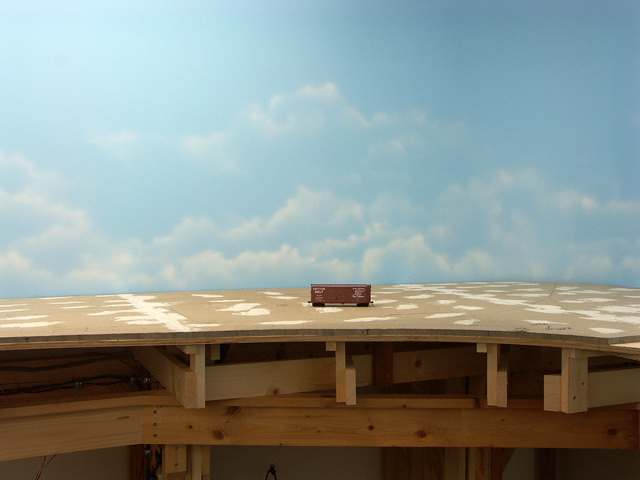
I need to be thinking about putting up parts of the fascia around the layout.  The fascia will be much more than just a nice piece of trim on the layout’s edge.  It will be supporting the various control panels, throttle plug-ins, beverage holders and various appurtenances as I may think of in the future.

But I can’t reasonably start any type of train operation until I get at least a few panels installed and a hand full of the throttle plug-ins.  Thus, I need some fascia.

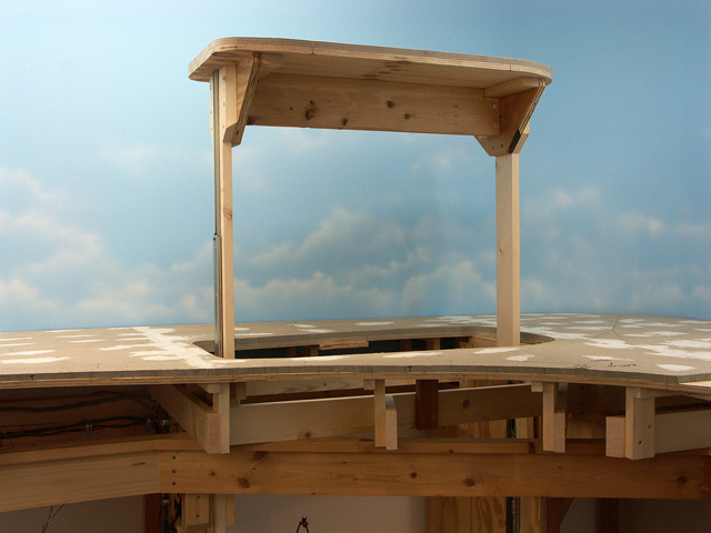
The fascia will average 8″ in height, the top undulating to match the terrain and elevation at any given location…pretty standard fare.  I plan to use Masonite hardboard for the fascia, and have been thinking of laminating two 1/8″ thick panels together.  My reasons for this two-ply configuration are twofold: I think working 1/8″ material around a tight radius will be much easier than using 1/4″, and the two plies should give me the rigidity of a single 1/4″ panel.

My general plan is to screw the first panel to support blocking on the benchwork.  Then I’ll come back and glue the second panel to the first using yellow carpenter’s glue.  Clamping the panels together until the glue sets is a bit problematic.  I’ll be able to clamp along the bottom of the fascia, but will probably have to use some screws along the top to clamp that.  The downside to that would be having to remove the screws and fill all those holes afterwards if I wish to keep the fascia “clean”.

I’d love to hear from you folks out there if you have other ideas or suggestions as to how I might accomplish this task.  It would be good having alternatives to think about.  Any thoughts would be welcome, everything from materials to methods.

-Jack

Assaulting Homasote Joints

Regular readers will recall the disaster I incurred in my attempt to use a belt sander for tapering roadbed and truing joints between Homasote sheets (Banning the Belt).  In laying the sub-roadbed for Monterey, which is essentially a Homasote tabletop, I was faced with three wide joints with a significant mismatch in height.  As I’ve mentioned several times, Homasote isn’t known for its consistency in thickness.  These height mismatches between panels were as great as a 16th of an inch…much too great to simply lay track, or even roadbed and track over.

Hand sanding large expanses of Homasote isn’t practical.  It just doesn’t sand like wood.  This past weekend I knew I had to get these joints matched up before track laying could commence.  So I tried another approach to the problem.  I had a Surform tool in my toolbox so I tried it out.  Surprise, it actually started shaving off the Homasote.  Now, it wasn’t pretty.  It actually grabs little chunks of Homasote and rips them out.  The tool clogged quickly, but a small stiff bristle brush worked well to clean it up.  I didn’t want to simply do a quick taper right at the joint, but rather I wanted a gradual taper of at least 3-4 inches in width.

Once I got it fairly close with the Surform tool, I decided to try my finish sander for the final sanding.  I attached some 50 grit paper (pretty coarse for a finish sander) and started working the surface.  This worked out much of the roughness created by the Surform tool.  I worked it for quite some time and ended up with a pretty decent taper and surface.

The final step was to smear a coat of drywall mud over the joint, building up from the formerly thinner side of Homasote up to the joint.  I’ll sand this down tonight and apply another coat.  After doing this two or three times, I should have a pretty decent joint between the panels and will be satisfied.

It was several hours of work, but in the end I think it’ll be worth it.  Did I mention the layer of fluffy dust over that area of the room to clean up?

On another note, I had intended to keep my electrical wiring current with the track laying.  But I’d let the wiring slip over these past couple months.  Surveying under the layout, I realized that there were about two dozen sets of track feeders that hadn’t been connected to the power bus yet.  I took the first step in installing the terminal blocks at each location (which serve as the interface/disconnect between the feeds and the bus), and I crimped spade lugs on all of the feeders.  Over the next weekend or two I’ll make taps into the power bus and run the heavy gauge taps to the terminal blocks.  My method, though tedious, works quite well and should result in dependable wiring that will also be easy to troubleshoot when necessary.

All in all, a pretty busy weekend especially since I was away from home most of Saturday.

-Jack

Those Optical Detectors

There are six hidden staging tracks serving the Louisiana Central.  Since the tracks are concealed from normal viewing, I decided to use optical detectors at each track to determine occupancy and the locations of trains.  Typically each track has two or three detectors near its end, and one at the entrance marking the fouling point.

Two of those staging tracks are in Monterey, one each for the IC and the T&P.  This weekend I completed the wiring for the photo-transistors and infrared (IR) LEDs, and their connections to the circuit board serving this area.  The fascia panel with the indicators isn’t built yet, so I soldered a couple leads to a red LED indicator and temporarily jumped it across the various output terminals for testing.  I’m happy to report that all the detectors worked perfectly without a single adjustment necessary.  This is somewhat a milestone in the electrical/electronics portion of the layout construction.  There are two more circuit boards over at the Willis side to handle the rest of the staging tracks.  I’ve got most of the photo-transistors already wired, but I need to get all the IR LEDs installed.  Benchwork for the Spencer logging operation can’t proceed until that work is done as most of the staging track is below that, and I want the system complete and operational before starting this new benchwork.

I had a busy weekend working on the layout.  In addition to the above, Wayne and I got the remainder of the sub-roadbed installed in East Monterey (not an official designation).  This area is around the corner from Monterey itself and will support the mainline entering town as well as a couple businesses.

I also got some roadbed laid near the end of the Monterey yard and I took care of a half dozen little tasks that I’d been putting off.  Overall, a good weekend.

Finally, my scheduled visit by a guest from Florida was cancelled due to some family health issues, but I got a semi-surprise visit instead from a co-worker, Van Thomas.  Van has been hearing about my construction for the past couple years and he decided to come over to see what this was all about first hand.  I think he enjoyed the visit, despite the hot and heavy construction going on during his stay.

-Jack

Monterey Yard Sub-roadbed Complete (and other things)

Things have been pretty busy around the Louisiana Central these past weeks.  Since completing the lift-up access section a few weeks ago, I’ve gotten the remainder of the sub-roadbed down for the yard at Monterey.  This completes the benchwork along the east wall of the building and represents about three-fifths of the total area of layout.  The west wall and the second of the two peninsulas will not have so much “table top” sub-roadbed, but will be heavy in the single track variety as this is where much of the mainline is located.

This past weekend, Wayne and I mocked up the Spencer Lumber Company’s line up into the woods.  This is the trackage that will be over (and will conceal) the three track staging yard along the west wall of the layout.  I’ve had concerns over the accessibility of these tracks since the day I started construction.  The track will be reachable from below the benchwork, but not easily visible.  I’m hoping that the crude mock-up we’ve erected will enable me to study the concept satisfactorily, and to make the decision to go with it or not.

Next weekend I’m expecting a visit from a fellow hobbyist from Florida.  I had planned to clean and straighten up around the layout in anticipation of his visit, however, lack of time will likely kill that plan…hope he understands.  I also need to take some time to visit the library that is currently hosting an exhibition of photographs taken by local photographer Forrest Becht.  Forrest takes images of many things, but railroads are his specialty and I always enjoy viewing his work.

There’s a fellow up in Canada, Trevor Marshall, that is building an S scale pike based on a Canadian National branchline set back in the 1950s.  I believe I’ve mentioned him before in this blog.  Anyway, Trevor maintains a blog chronicling the construction and operation of his mini-empire, along with other little tidbits about what’s going on in his world.  I really admire Trevor’s approach to the hobby and many of the things he does to model the CN branch and to enhance his operations.  I also enjoy his writing style and the variety of topics he rambles about.  If you’d like to give his blog a look-see, you’ll find it here: Port Rowan in S Scale.  To quote Trevor, “Enjoy if you visit“.

-Jack

Trains Roll on the Attighany Sub

Back in April I mentioned the possibility of continued operations on the late Lou Schultz’s Chesapeake and Ohio layout (Maybe the Sun Hasn’t Set).  Well possibility became reality this past Saturday as many of the former operating group assembled once again in Covington.  Yes, trains once again rolled on the Attighany Sub (an unofficial term often used for the layout).

We ran what was termed a “test” session.  We had a reduced crew of 16 and ran a four hour session.  The local organizers had pre-staged the layout and cleaned the track.  The fast clock was plugged in at 12:01 p.m., and trains started moving.

As was expected, there were a few glitches, some operational, some electrical/mechanical.  But considering that the layout had been dormant for over a year and that no one there had ever staged the layout before, things ran surprisingly well.

It was great seeing old friends again.  I think I speak for most everyone in saying that we want to continue doing this.  But there was also a sadness in not having Lou, Bill and Shawn present.

Our heartfelt thanks go out to Lou’s wife, Dee, and the family for their kindness and the opportunity to keep Lou’s dream alive.

On the way back home, Wayne Robichaux and I analyzed the session and stopped to partake of a meal at the Lagniappe Restaurant in Denham Springs.  What a way to spend and end the day . . . a fine day indeed!

-Jack

Sneaking Into Monterey

One can now sneak into Monterey via a subterranean entrance.  I completed the lift-up section this weekend.  Now I’ve got reasonable access back to the tail track of the wye and the surrounding area.

Lift-up section - closedAbove: Here’s the lift-up in the closed position.  The seams are very tight (merely the thickness of a jigsaw blade).  The wye will be to the right of the lift-up.

Below: And here’s the view of the lift-up in the raised position.  The center cross brace is about 3″ above my head.  I can comfortably reach the corner over to the right now.

Lift-up section - openThe drawer slides I used have release latches in them and it’s easy to lift the hatch and support legs completely out of the hole.  After setting the assembly aside, the area all around the hole is completely unobstructed.  I also can then stand on a stool if need be to enable an even further reach into the corner and to get my tired old eyes closer to the work.  That might be useful when scenery work begins.  There are a few more photos you can view here on the main website.

The lift-up works quite well, is easy to operate, and I’m very pleased with it.

-Jack

A Visit to the Narrow Gauge

This past weekend Wayne Robichaux and I paid a visit to a friend, Bob McNeese, to pick up some Homasote left-overs that he had from his nearly finished layout.  While there, Bob gave us a tour of his pike and I must say, it is something to behold.

It’s in Sn3 scale and is generally based on the former Rio Grande’s narrow gauge operation in the New Mexico/Colorado area.  The layout has a couple small yards, and silver mines abound.  The structures are superb, the layout’s level of detail is quite high and the scenery is spectacular.  There was simply no way to take it all in with just one visit and I’ve already told Bob that I need to visit again to continue my observation.

The proponents of S scale often tout the fact that it is the “ideal” scale, and I have to agree.  I love the size with respect to actually being able to see the finest details, yet still small enough to get a decent sized layout in a modest space.  If I didn’t have 50 years worth of HO collected and was just getting started, I’d have to give S scale some serious consideration.

On the Louisiana Central, a modest amount of work has been accomplished since my last post.  The framing around the lift-up access hatch is done and the drawer slides are installed.  I need a couple more hours to complete the framing required on the hatch section itself to connect it to the drawer slides.

I’ve completed the short run of sub-roadbed needed to tie the Texas and Pacific trackage from staging, into the main sub-roadbed at Monterey.  I’ve extended the T&P track from staging onto the visible portion of the layout, just shy of the yard.

And I’ve advanced the track into Maynard a bit.  I’ve been preparing the two switches that will be required there, and should have those installed shortly.  Further progression of the mainline will be a bit down the road.  I want to start work on the Spencer Lumber Company’s trackage into the woods and the reload point before putting in the LC trackage.  This is because the LC track will be in the foreground and I prefer working from the wall out toward the aisle.  Hence, the logging line needs to be first up.

Stay tuned…

-Jack

Multi-front Expansion

I’ve been working in two different areas of the layout these past weeks.  As I mentioned a couple posts ago, the Louisiana Central mainline now extends from Willis Junction (the point at which the mainline enters the layout from staging) to the east end of Maynard.  This past week I completed the roadbed through Maynard along with the roadbed required for the two industrial switches in town.  The area is now ready to lay track, possibly starting this weekend.

Here’s a direct link to the layout trackplan.

The other area seeing heavy construction is the east end of Monterey.  I’ve got the sub-roadbed extending from the room corner (where the mainline will curve around to enter Monterey) to the yard ladder.  This section of layout will also contain a wye to be used to turn equipment when required.  This entire area is essentially just a Homasote topped table.  Since the benchwork here is quite deep (the corner being out of reach), I’m providing a lift-up section adjacent to the wye, which will provide good access to the distant area.  The hole has already been cut, and my next step is some framing around the bottom of the opening to support the closed hatch.  I’ve procured some heavy-duty, full-extension drawer slides to use for the lift up guides, à la Charlie Comstock’s method which has been featured in the Model Railroad Hobbyist magazine.  When I get it finished (assuming it works as intended), I’ll post a couple photos showing it.

Come to think of it, I need to take some photos of the present state of layout construction.  I haven’t posted any new pics since back last December and there has been nice progress since then.

-Jack

Maybe the Sun Hasn’t Set

Maybe the sun hasn’t set over Lou Schultz’s Chesapeake and Ohio layout just yet.  Lou’s family has indicated a desire to see the layout live on and has extended  an invitation for Lou’s operating group to conduct further operating sessions.  Matt Hardey has taken the bull by the horns, along with several others and the “exploratory committee” sat down together this past Saturday at DiMartino’s Restaurant in Covington for a fine meal and to do some planning for the session.  Present were Matt, Mike Walsdorf, Sam Urrate, Johnny Miranda, Wayne Robichaux and yours truly.

The late Bill Williams, known as the Gestapo among the crew, was the Chief Clerk for Lou.  He spent considerable time before each session staging cars and setting up the waybills.  Unfortunately, no one else has a full grasp for all that Bill did, so the main topic during the meal was how operations could be simplified and pre-staging eliminated (or at least substantially reduced).  Several ideas were presented that were deemed worthy of a trial.  The “shake-down” session has been tentatively scheduled for mid May.  I, for one, will be tickled to be back up in the attic again.  Even though Lou, Bill and Shawn won’t be there in person, I’m sure their spirit will be.

And speaking of that, several of the guys had been to Lou’s house earlier in the week to check things out on the layout.  Lou’s wife, Dee, was out puttering around in the back yard.  The fellows were down at the far end of the attic when they heard someone trudging up the stairs (wooden stairs lead up to the attic).  One of the group shouted out that they were down at the end by Alderson, but no one came forth.  Puzzled, one of the guys went to the stairs.  No one was there.  He went down and found Dee, who said she had been in the yard the entire time.  Soooo….who was there (sound of squeaking door in background)?

Maybe I’ll be busy that Saturday……

-Jack

1st Train Rolls on L.C.R.R. Main

This past weekend saw the first train traverse the mainline between Willis Junction and the outskirts of Maynard.  Prior to this the only completed trackage was that between Bude (staging) and the LC-IC crossing at Willis.

ALCO locomotive no. 5582 grabbed a couple boxcars and made several trips out and back to test the newly laid track.  Track Foreman Smylie McDermott declared, “It’s good enuf”.

Crews will now install a couple spurs in Maynard to serve two new customers, immediately creating revenue for the line.

Statistical note:  The distance between Willis Junction and Maynard is about 3/4 of a (scale) mile, a bit less than a third of the total (visible) mainline to be constructed.

-Jack

Bridging the Gap (rehashed)

I’m getting close to the point of needing the bridge across the doorway into the train room.  Originally I had planned to use a swing gate for this purpose.  Indeed, the track plan still indicates this as the intention.  However, I decided quite some time ago that a swing gate wouldn’t be ideal in this particular installation (read about that here).  If you took time to read the original post, then skip the next couple paragraphs, otherwise let me explain further.

One of the key scenic features that I’ve planned for the layout is a long, low trestle crossing a semi-swampy waterway…something quite common in south Louisiana.  In the early days of fiddling with the track plan, I decided that the only proper place for this would be near the town of Monterey, the western terminus of the railroad.  Monterey is located near the Mississippi River in a low-lying area just south of the Angola State Penitentiary.  As such, I decided that the minimum benchwork width for this needed to be 12″ so that at least a semblance of a waterway could be modeled.  The final location of this area ended up right in front of the entrance into the train room.

A (swing) lift-up wouldn’t work here as the benchwork is angled across the entry, and when swinging the section up, it would crash into the lighting valence already in place.  Hence, the swing gate was decided on.  But there are problems with that.  When I started studying the needed design in detail, it became apparent that it wouldn’t be practical to build something that, when open, would rest up tight to the benchwork, allowing a reasonable passage in the aisle way.  The combination of the 12″ width and the required hinge location point make this infeasible (look at the track plan on the website to see what I’m talking about).

So next, I decided that a swing down bridge might work.  Some preliminary drawings I sketched show something that would probably work pretty well.  The plan is to hinge it from a point several inches behind the joint, and have the bridge section swing down into a “box”.  This box would protect the section while down.  I likely could even come up with something to make it easier to lift such as one of those gas pressurized struts similar to those commonly used in the automotive industry.

This is my most likely candidate.

One other concept I’m revisiting is a lift-up section that would have the entire bridging section lift rather than swing (a vertical lift bridge).  I would use telescoping drawer slides at each end for this to work.  I think the actual bridge design and construction would be rather simple.  I was originally concerned about overhead clearance, but that may not be an issue after all.  However I’m concerned about the final weight of the section.  I suspect that some sort of counterweight system would have to be employed so that the bridge would raise easily, preferably using a single hand.  That makes the design considerably more complicated, though not insurmountable.

I am doing further research on that concept presently.

Once I have a decision, I’ll probably get started with the bridge.  The benchwork at Monterey is well along, but it will be pointless to spend energy and time putting in track until the bridge is in place, as you can’t leave town without it.

Write if you have ideas or comments.

-Jack

Clamping Down on Wires

Art Houston sent me an offline comment yesterday in which he mentioned drilling holes through the benchwork joists to act as wire raceways.  I responded to that with the method that I’m using for my wiring.  After thinking about it this morning, I decided I’d share my method with the rest of you.

When I erected my basic L-girder framework for the layout, I used a single “keeper” joist at each leg set location for the purpose of holding the L-girders in position.  As I’ve progressed with the sub-roadbed around the layout, I’ve added joists on approximately 16″ centers to support the risers and sub-roadbed.

Many modelers drill holes through their joists in which they then pull the wires for the various electrical circuits around the layout.  The problem I have with that is twofold: (1) I don’t have all the joists in place so that the wire can be pulled through. (2) Making changes to the wiring becomes more laborious if one has to pull wiring in or out of all those holes.

My solution was to create a series of hangers for the wiring.  For this I use simple EMT conduit clamps attached to the web of the L-girders.

Conduit ClampThese clamps are available in many sizes; I’m using both 1/2″ and 3/4″.  I buy them in boxes of 100 at Home Depot and they are relatively inexpensive in that quantity.  I use a single 3/4″ hex head sheet metal screw to attach the clamp, oriented in a vertical position, with the screw at the bottom.
Sheet Metal ScrewI like these screws as I can drive them into the soft pine wood, using a nut driver, without first drilling a pilot hole.

Generally I space the clamps about 12″ apart, with additional clamps located where needed.  I am running my power buses at the back L-girder near the wall, and my control buses at the front L-girder near the aisle.  I also have some special wiring in a couple locations for the optical detectors on the staging tracks.  This is a 25 pair telephone cable that I’m suspending in it’s own set of 1/2″ conduit clamps attached to the bottom of the joists.  I’ve already had to make changes in that wiring and the clamps made it a snap.  Merely loosen the screw at the clamp and slip the wire in or out, then re-tighten.

While not very high tech, this method has served me well on my last couple layouts.

-Jack