What with all the functions and family things going on at this time of year, I’ve scarcely had time to do anything of great magnitude out in the train room for several weeks now. I have however, managed to pick away at lots of little things. I thought I’d post this quick update of what’s going on.
I’ve mentioned a couple times that I needed to start modifying all of my Shinohara code 70 switches to be “DCC friendly”. I have about 40 or so of these things to work on, and trackwork has come to a grinding halt until I get some of them done. A drill press should make the task considerably easier. I’ve had a large floor model press for years, however it simply has too much run-out in the chuck (or perhaps the arbor) for it to be of use with tiny wire size drills. So I ended up purchasing a small table-top model that I think will be better suited to the task. Upon arrival and assembly, the first realization was that I didn’t have anything suitable to sit it on out there in the train room. So I cobbled together a small table from scraps, slapped a coat of paint on it, and now have a stout, compact place to operate the press on. I chucked a pin vise adapter into the machine and inserted a number 70 drill bit. I’ve only run it for a minute or so and haven’t drilled any holes yet, but I can tell the bit is running much truer than it would have in my large floor press. Hopefully I’ll be able to start work on the switches soon.
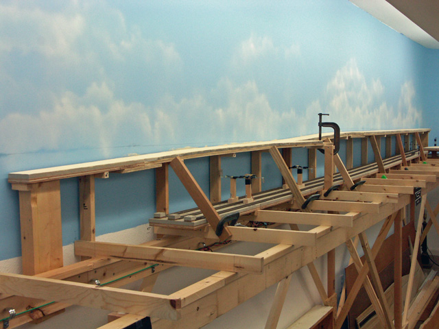
Wayne Robichaux came over to lend a hand and we’ve installed the first 15 feet of fascia to the layout edge. It sure makes a difference in the appearance, with even Wayne remarking how it made the layout look like a real layout (whatever that means….). Nah, just kidding, I know what he’s getting at….even unpainted, it adds a nice finished look to the edge. We will install perhaps another 20 feet or so along the mainline between Willis and Maynard. I’ll hold off installing it in other areas until all track is down and wired, and the switch motors are installed.
I keep crawling under the layout to connect more track feeders to the power bus. I’m connecting feeders to each switch and to almost every length of flex track. That’s producing a LOT of feeders. The only track sections without feeders are those soldered to an adjacent section that has a feeder. I hope this pain now will be rewarded years down the road with good, dependable electrical performance.
I’ve another half dozen minor tasks that I’ve completed, but this post is becoming long-winded, so I’ll spare y’all the details. Now that I have some fascia applied, I can begin installing some of the fascia mounted items such as throttle plug-ins and switch panels. I’ll also have car card boxes, work shelves and a few other odds and ends on the fascia, but those will come much later when we are nearing operation.
I’ll post a photo or two in the next week or so when we finish the fascia project.
I’d like to wish all of you a very Merry Christmas and a great New Year!
-Jack