As I’ve mentioned before, electrical things usually come fairly easy to me. However sometimes those little electrons do their best to stymie me, as I illustrated in another post. This past week I ran into another of those little gremlins.
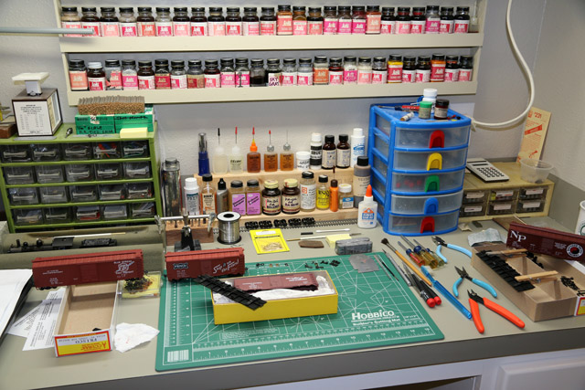
We’ve had a lot of rain these past few weeks, so I thought it would be a good opportunity to catch up with the under table electrical work. I had put in a good bit of trackage over in Monterey, which included the turning wye. It all had to be connected electrically, so I crawled under the layout and started connecting about a jillion track feeders.
When I initially started my track installation and wiring, I kept a small battery/buzzer device connected to the track which would sound the alarm if I happened to connect something in a way it didn’t like. However, once I installed my PSX circuit breakers (CB boards), I would get a constant alarm as the device would back-feed through the CB board circuitry. So, being lazy, I unclipped the device from the track rather than disconnect the main feeds from the circuit breaker. I was quite careful though, and all my wiring is color coded, so I didn’t anticipate any problems.
Well, I suppose I should have anticipated them because when the wiring was completed and the power was flipped on, the fault light on the CB board lit up with complaint. Arrghhh!
The last trackage installed had been the wye. So back under the layout I went, disconnecting track feeders one at a time, starting from the far end. After all the wye feeders were disconnected, the fault light remained on. So I started disconnecting the rest of the feeders to the mainline, and yard trackage. I disconnected every feeder and the light kept glowing. Now what? The problem had to be in the track itself. So I disconnected the CB board and started poking around with my little buzzer device. I eventually determined that the problem was somewhere in the wye trackage.
One tail track of that wye crosses the mainline utilizing a Walthers/Shinohara 90 degree crossing. The crossing itself had been a big concern initially because during manufacture it had apparently been removed from the injection mold prematurely and was significantly warped. I contacted Walthers for a replacement but they had none in stock, and had no ETA for new inventory. Checking around quite a few mail order shops, I was unable to locate one. It tested out OK electrically, and I could press it down flat to the table against it’s will, so I decided to go ahead and try using it. I stuck it down with adhesive caulk and soldered the connecting tracks to it, and this seemed to tame it.
With that background, I strongly suspected that the crossing might be the culprit. So I held my breath and sliced through one of the rails between the crossing and the wye switch. I figured that would at least tell me whether the problem was in the wye trackage, or in the crossing. The buzzer informed me that the problem was in the wye. Rats! So I figured I needed to start isolating the switches. With great difficulty, I managed to slide the rail joiners of the first switch until they contacted a tie. But they wouldn’t slide quite far enough for me to lift out the switch. So I carefully cut down through the rail joint and rail joiner on each rail. Still no joy. In the meantime Wayne had come over and after looking things over, was just as puzzled as I.
I just stood there leaning on the layout, wondering just what in the world was happening here. Then I had the epiphany. One of the three switches and it’s tail track comprise the turning section of the wye, i.e. the reversing section. It is necessary to gap all four rails of that switch to isolate it from the other wye trackage. I had dutifully sliced through these rails and filled the gaps with bits of styrene, filed and shaped to the rail contour. My realization was that I had probably sliced through the rails on the wrong side of the internal jumpers built into the switch. Again I held my breath and made a single cut through the crosstie that I suspected would surround said jumper, then hooked up the buzzing device. Nothing…as in success! Such a rookie mistake. I had failed to note the internal jumpers (visible from the underside of the switch) before gluing it down. It also happened to be the last track assembly that I had installed.
I carefully reconnected all the feeders throughout (with the sound maker hooked up), then set about repairing all the damage I’d done to the track during my trouble shooting. Fortunately I was able to slide those shortened rail joiners back onto the mating rails, then soldered everything to keep it in place. The initial cut at the crossing was aligned with the aid of a couple tiny brads driven into the roadbed (they’ll have to be painted over or otherwise concealed later), then all soldered. A piece of styrene was inserted into the severed crosstie to keep the gap from closing. And finally, I had to run a wire jumper to the short, now isolated rail at the offending switch and connect it to the barrier strip below. I reconnected the track power, and hit the master switch. Success!, the fault light was out and the Alco on the siding burbled to life.
I won’t be doing anymore track or electrical work without my buzzer connected.
-Jack